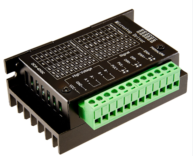
A stepper motor controller operates by converting a sequence of input pulses into precise increments in the mechanical shaft’s position. Each pulse impels the shaft through a predetermined angle, allowing the motor’s position to be directed to one of these steps without necessitating any feedback sensor, a configuration referred to as open loop stepper motor control. The success of this control method hinges on careful sizing of the motor in terms of torque and speed to suit the specific application. Stepper motor control utilizes this sequence of input pulses to dictate the motor’s movement to attain a desired position or speed.
In stepper motor control, constant voltage drives are typically employed to apply a sustained positive or negative voltage to each winding for propulsion. However, it is crucial to recognize that it is the winding current, not the voltage, that exerts torque on the stepper motor shaft. The relationship between the current (I), applied voltage (V), winding inductance (L), and winding resistance (R) is integral to understanding these systems, and they are often referred to as L/R drives. Achieving high torque at elevated speeds necessitates a substantial drive voltage paired with low resistance and low inductance. In cases of low voltage resistive motors, a higher voltage drive can be used by simply introducing an external resistor in series with each winding, although this approach is deemed less efficient due to power wastage and heat generation.
On the other hand, constant current drives are engineered to maintain a constant current in each winding, rather than a constant voltage. With each new step, an initial high voltage is applied to the winding, leading to a swift rise in current within the winding due to the equation dI/dt = V/L, where V is significant. Stepper motor controllers typically monitor the current in each winding by measuring the voltage across a small sensing resistor in series with the windings. When the current surpasses a designated limit, the voltage is turned off, and when it falls below this limit, the voltage is reinstated. This approach ensures a relatively constant current for a specific step position. While it does require additional electronics for current sensing and control, it permits stepper motors to be driven at higher torque and swifter speeds compared to L/R drives.
For enhanced system resolution, reduced noise, and smoother motion, Portescap’s Microstepping Drives offer substantial advantages. The power stage in these drives is meticulously designed to accommodate motors with low electrical time constants, resulting in exceptional dynamic performance.

Stepper motors can be an advantageous choice for many applications, and when they are suitable, they will be a lower cost option than servos. For applications where accurate single axis or limited multi axis motion control is needed, stepper motors, drives, and controllers (especially PLCs) used in conjunction with position switches and/or an encoder will reliably operate machinery at about 25% the cost of servo motor systems.
KUKE insists on supplying only original electronic components, such as high quality stepper motor driver. If you have any question, please contact KUKE immediately.